Hardware analysis
Description of hardware
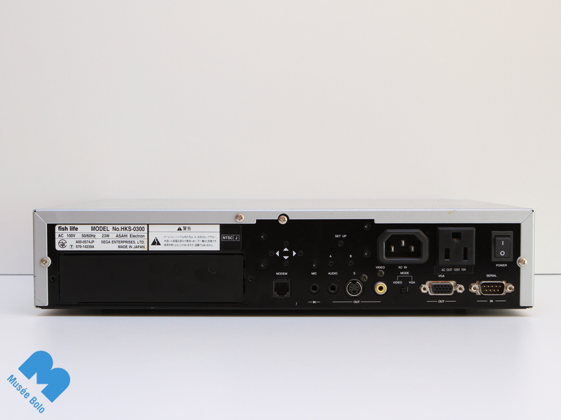
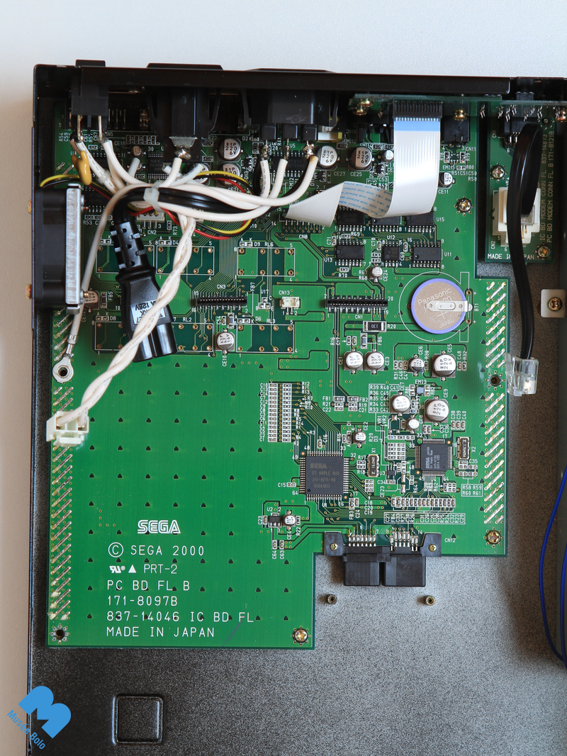
The electronics of the Sega Fish Life are based on the Dreamcast. The external connections are as follows:
- Serial port, DB-9
- Modem 56k/bit, RJ-11
- Standard 15-pin VGA connectors, S-Video mini-DIN 4-pin and Video Cinch
- Audio output jack 3.5 mm
- Microphone input jack 3.5 mm
- 4 directional buttons and 3 command buttons
- 115 V power supply input
- 115 V power supply output for LCD screen
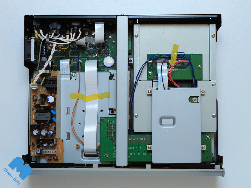
Within the body, there are two Dreamcast controller ports. As these ports cannot be accessed once the casing is closed, they were not intended to be used in the normal functioning of the Fish Life, but they were most likely used during development or for testing.
There are differences in the hardware between the Fish Life and the Dreamcast:
- Two additional cards:
- Adaptation card of the GD-ROM drive connector;
- Interface card with external devices;
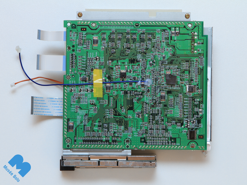
- A blue wire on the motherboard which inhibits the Dreamcast mode, if connected, and prevents the launch of Dreamcast games;
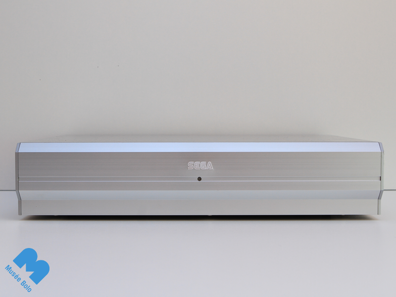
- Spacious metal casing for professional use.
Repairs
Musée Bolo’s Sega Fish Life was not functioning correctly and required a conventional repair. The problem was caused by a faulty capacitor. The biggest challenge was identifying the issue. Replacing the faulty part was a relatively straightforward operation.
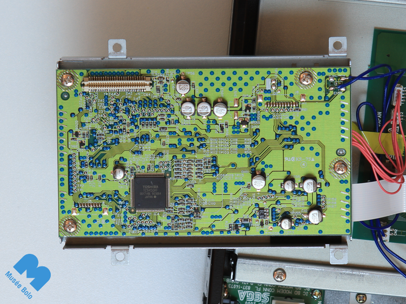
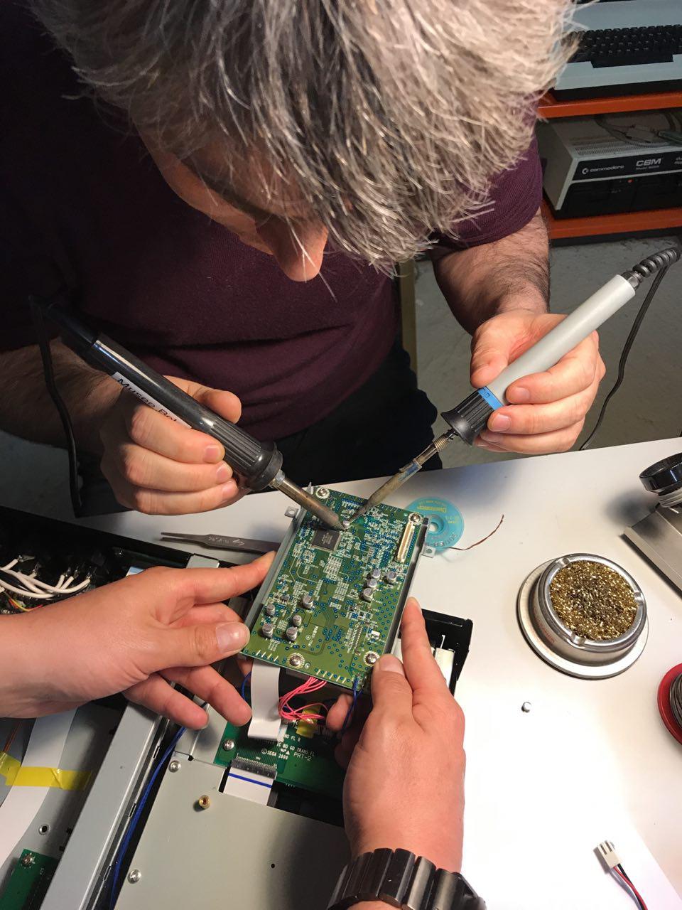
Once the capacitor was replaced, the Sega Fish Life was as good as new.
Changes made
First of all, the power supply output for the LCD screen was detached to avoid any potential catastrophe when connecting a 115 V screen.
We replaced the original power supply with a 230 V power supply from a European Dreamcast to avoid any false manipulations which could be damaging.
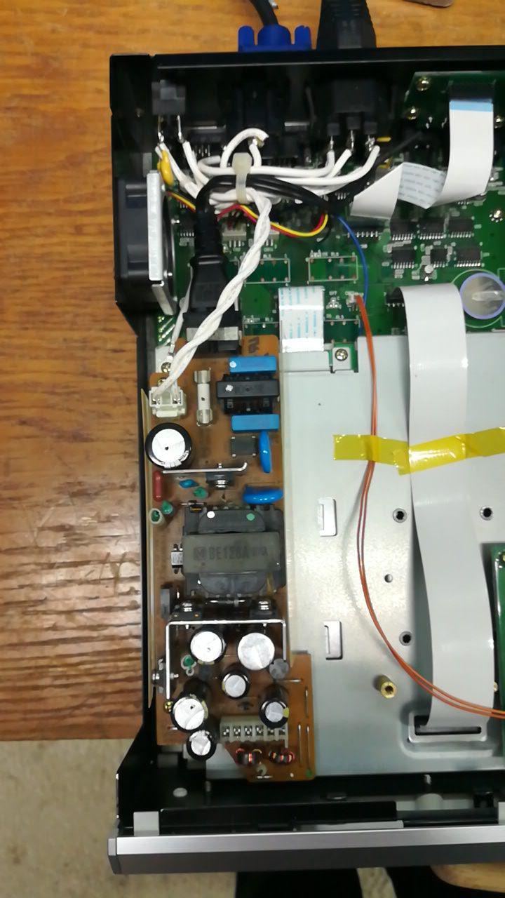
Clearly, this is a non-standard modification as the Sega Fish Life was principally sold in Japan where the network’s voltage is 115 V in alternating current.
Extracting the BIOS content and the Flash system memory.
In order to optimise the hardware preservation, we wanted to extract the BIOS content and the Flash system memory of the Sega Fish Life. To achieve this, we decided to use the open-source operating system NetBSD which is known to be compatible with numerous platforms, including the Dreamcast’s SH4 microprocessor. From a strictly hardware point of view, the Fish Life is essentially a Dreamcast with a few different inputs/outputs. We therefore adapted the configuration of NetBSD’s kernel to include the basic tools required to communicate with the Fish Life’s main unit using the DB-9 serial port.
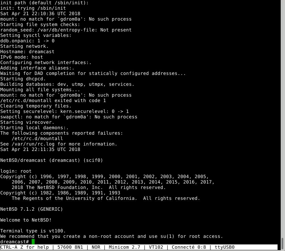
Thanks to NetBSD’s very detailed documentation for the Dreamcast, we were able to easily access the BIOS and Flash content which were directly readable at specific memory addresses. There was the risk of issues with the data transfer. However, we were able to get around this by copying the data in sections to be recombined afterwards.
Analysis of various reference numbers
| Type | Model No. | Part No. | Serial No. | JATE No. |
|---|---|---|---|---|
| Main unit |
HKS-0200 (alone) HKS-0300 (with screen) |
670-14239A[26] | 01006576 (Musée Bolo) 01006353[59] |
A00-0574JP[60] |
| Screen | HKS-0100 | 670-14224A[26] | 01006280[26] 01006257[27] |
N/A |